Solar Panel Outputs and Parameters
When examining the outputs of a solar panel, it’s essential to understand the components and specifications that influence its performance and efficiency. This guide provides an in-depth look at the junction box, key electrical characteristics, operational parameters, and mechanical properties of solar panels.
Junction Box and Bypass Diodes

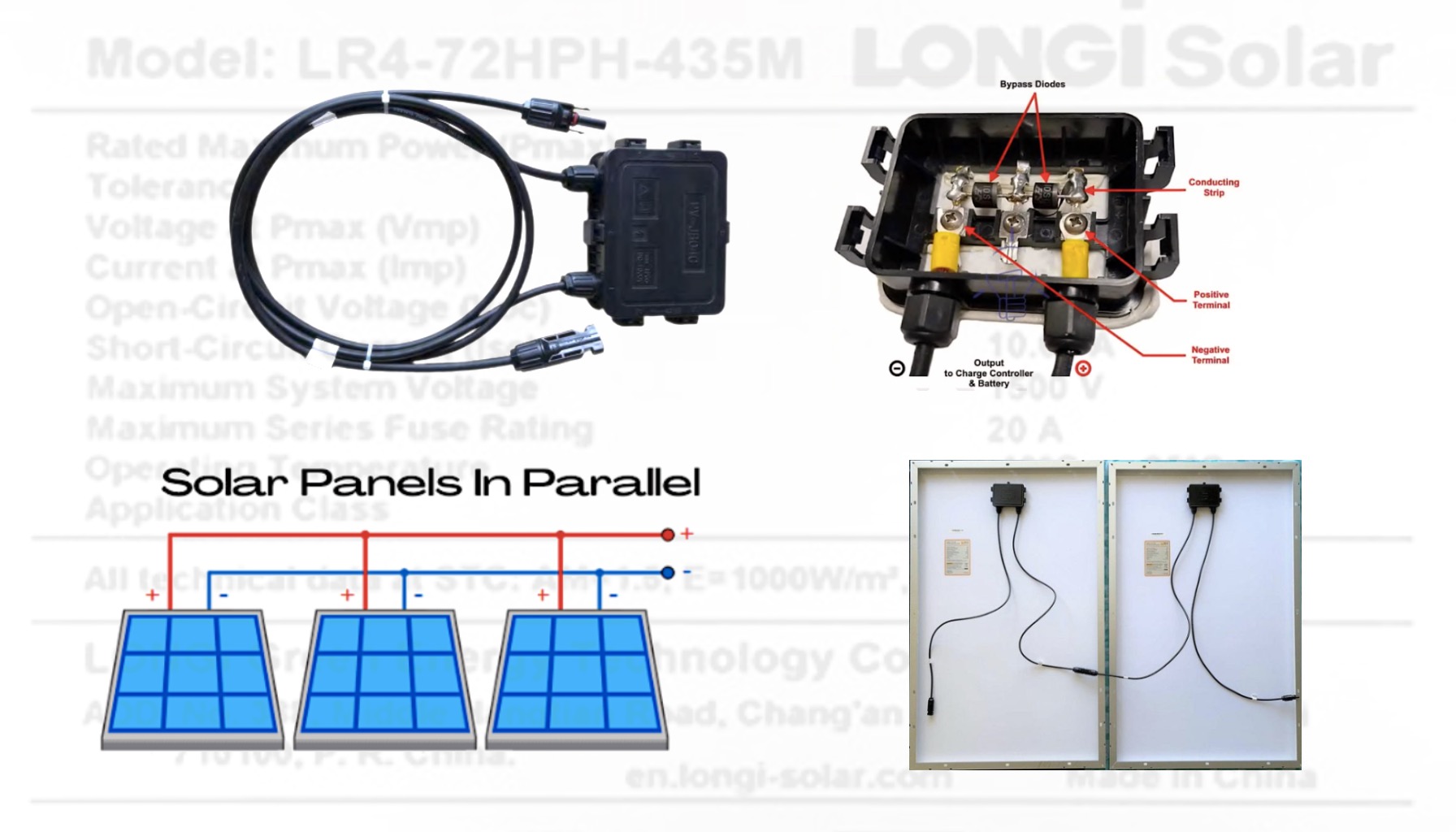
On the backside of a solar panel, you will typically find a junction box, which may contain one or more bypass diodes. These diodes protect groups of solar cells from shading and reduce power loss. Ideally, each cell would have its own bypass diode, but due to cost considerations, diodes are only installed on groups of cells.
Important Note:
Bypass diodes do not prevent energy from flowing from the battery back to the solar panel when there is no sunlight. To block this reverse current, a blocking diode is used, often integrated into the solar charge controller.

From the junction box, two cables with MC4 connectors (or sometimes other types) emerge. High-power solar panels (200W and above) always include bypass diodes and cables, whereas low-power panels (below 200W) may only have a junction box without cables and occasionally lack bypass diodes.
Key Solar Panel Parameters
The main parameters of a solar panel can be found on its rear label and in the datasheet provided by the manufacturer. These specifications are typically measured under Standard Test Conditions (STC), which assume an irradiance of 1000W/m² at a cell temperature of 25°C.

Electrical Characteristics:
- Maximum Power (Pmax): This indicates the highest power output the panel can achieve under STC, typically 435W.
- Open Circuit Voltage (Voc): The maximum voltage available from a solar panel when there is no load attached, usually 48.7V.
- Short Circuit Current (Isc): The current through the solar panel when the output is shorted, typically 11.39A.
- Voltage at Maximum Power (Vmp): The voltage when the panel is delivering its maximum power, typically 40.9V.
- Current at Maximum Power (Imp): The current when the panel is delivering its maximum power, usually 10.64A.
- Module Efficiency: The efficiency of the panel in converting sunlight to electricity, often around 20%.
Operational Parameters:
- Operational Temperature Range: The range of temperatures in which the panel can function effectively, typically -40°C to +85°C.
- Power Output Tolerance: The range within which the actual power output may vary from the specified Pmax, often 0 to +5%.
- Maximum System Voltage: The highest voltage that can be applied to the panel safely, usually 1500V.
- Maximum Series Fuse Rating: The maximum current rating of the fuse that should be used in series with the panel, often 20A.
Temperature Coefficients (STC):
- Temperature Coefficient of Isc: Reflects how the short circuit current changes with temperature.
- Temperature Coefficient of Voc: Typically -0.27%/°C, indicating how the open circuit voltage changes with temperature.
- Temperature Coefficient of Pmax: Usually -0.35%/°C, showing how the maximum power output depends on temperature changes.
Mechanical Loading and Durability
When selecting solar panels, understanding their mechanical properties and load ratings is crucial for ensuring optimal performance and durability
Mechanical Properties:
- Cell Orientation: 144 cells arranged in a 6x24 grid.
- Junction Box: IP68 rated, providing robust protection with three bypass diodes to ensure reliable performance.
- Output Cable: 4mm² cables with lengths of 400mm (+) and 200mm (-) for easy connectivity.
- Glass: 3.2mm thick tempered glass with a special coating to enhance durability and light transmission.
- Frame: Made from anodized aluminum alloy, offering strength and corrosion resistance.
- Weight: The panel weighs approximately 23.3 kg.
- Dimensions: The panel measures 2094 x 1038 x 35 mm.
Mechanical Load Ratings:
- Front Side Maximum Static Loading: The panel can withstand static pressure up to 5400 Pa on its front side.
- Rear Side Maximum Static Loading: It can endure up to 2400 Pa on the rear side.
- Hailstone Test: The panel is tested to withstand the impact of 25mm hailstones traveling at 23m/s, ensuring resilience against severe weather conditions.
Always refer to the manufacturer’s datasheet for accurate and detailed information.
Connecting Solar Panels: Parallel and Series
Understanding how to connect solar panels is crucial for optimizing your solar energy system’s performance. This guide covers parallel and series connections, the necessary connectors, and the effects on voltage, current, and total power output.
Parallel Connection of Solar Panels

In a parallel connection, the positive terminals of all solar panels are connected, and the negative terminals are connected similarly. This setup maintains the voltage at the level of a single panel while the current is the sum of the currents of all connected panels. The total power is the sum of the individual panel powers.
For example, consider a 435W solar panel with the following parameters:
- Maximum Power: 435W
- Voltage at Maximum Power: 40.9V
- Current at Maximum Power: 10.64A
Connecting three of these panels in parallel:
- Total Power: 435W + 435W + 435W = 1305W
- Voltage at Maximum Power: 40.9V
- Current at Maximum Power: 10.64A + 10.64A + 10.64A = 31.92A
Important Note:
When connecting solar panels in parallel, it’s recommended to use identical models or ensure voltage and current parameters differ by no more than 5%.
Required Connectors:
- For two panels: Two MC4 T-Branch connectors and one pair of MC4 connectors.
- For three or more panels: Three or more pairs of MC4 T-Branch connectors and one pair of MC4 connectors.
If you connect more than two panels in parallel, you might need extension cables to reach the common connection point. The combined current can become significant, so fuses are necessary for connections of three or more panels. Most connectors are rated for 30A. If the total current exceeds 30A, switch to electrical busbars made from stainless steel or brass instead of connectors.
Series Connection of Solar Panels

In a series connection, the positive terminal of one panel is connected to the negative terminal of the next panel. This configuration increases the voltage while keeping the current constant. If you need to increase the voltage of your solar system, a series connection is ideal.
For example, using the same 435W solar panel:
- Maximum Power: 435W
- Voltage at Maximum Power: 40.9V
- Current at Maximum Power: 10.64A
Connecting three of these panels in series:
- Total Power: 435W + 435W + 435W = 1305W
- Voltage at Maximum Power: 40.9V + 40.9V + 40.9V = 122.7V
- Current at Maximum Power: 10.64A
Important Note:
Like parallel connections, series connections should use identical models or ensure voltage and current parameters differ by no more than 5%.
Series connections are generally preferable where possible because increasing voltage rather than current reduces losses in the cables.
Conclusion
Whether you choose parallel or series connections, understanding your solar panels’ key parameters is essential for optimal performance and safety. By following these guidelines and using the appropriate connectors and fuses, you can design an efficient and effective solar energy system tailored to your needs.